Rigid Flex Circuits
The emergence of flexible electronic circuits has revolutionized handheld device design. Rigid flex circuits allow for more power to be packed into handheld devices, increase reliability and durability, provide a sleeker aesthetic, reduce the footprint of connectors and the number of wires required, and enable more functionality in a smaller package. While these benefits are obvious, a question that often arises is whether rigid flex circuits can be used in high-power scenarios. The answer to this is a resounding “yes”.
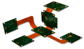
A rigid-flex printed circuit board combines both rigid and flex components, allowing it to conform to the shape of the device it’s placed in, while maintaining the strength of a solid PCB. Rigid-flex PCBs are commonly found in wearable electronics and mobile phone and tablet displays, providing a flexible connection to the base of the device, which can be bent, curved or folded. They’re also used in aerospace systems to improve thermal stability and reliability, simplify assembly, and lower costs.
To create a rigid flex circuits, the layers of a traditional rigid PCB are laminated to a flexible section with a conductive metal ribbon. The copper traces in the flex ribbon integrate directly into the layer stack as signals and are designed to remain strong under mechanical stress, including partial bends and deformations. To ensure that this happens, designers should use modeling tools to check component clearances and the ability of the ribbon to conform to the shape of a particular enclosure.
Can Rigid Flex Circuits Be Used in Power Electronics?
Once the ribbon layer has been modeled and the design has been finalized, fabrication can begin. The ribbon is either laminated to a thin layer of adhesive or laminated to unclad PI film, with the seed layer provided by chemical plating or by vapor deposition (sputtering). A photosensitive etch resist mask is applied to expose and develop the copper, which is then chemically etched in much the same way as it’s done for rigid PCB cores.
The finished rigid-flex circuit is drilled, plated through and etched to the same level as a rigid PCB and is then ready for assembly. Using the routing features in Altium Designer to define the electrical connections between the flex and rigid sections of the circuit board allows for a quick and easy process. This ensures that all of the signal traces and components are connected properly to avoid any issues with signal integrity, especially during high-power applications.
Handheld devices are growing in size and complexity, with many new devices requiring high-level capabilities that need to be squeezed into tight packaging. The flex section in a rigid-flex circuit takes up on average 20% or less of the available space, while simultaneously taking on the same amount of signal lines and power lines that are normally provided by a connector or wired solution.
Rigid flex circuits are therefore a great choice for power electronics, as they can be used to connect all of the critical components in a portable handheld device. However, the key is to work with an experienced design firm that can handle all aspects of your project. This includes preparing the rigid-flex circuit for manufacturing, providing engineering services that ensure the flex circuits can conform to the shape of the device they’re being installed in, and ensuring that all the layers are properly configured for optimal performance.